Adder bcd cheggcdn Adder adders circuits libretexts pageindex Adder bit circuit half make logic diagram comparator gates first electronics questions cout second only connecting solved puzzle which stack 8 bit adder circuit diagram
logic gates - How to make 2 bit or more half adder circuit - Electrical
Adder circuit diagram schematic bit full works figure Adder fitfab circuits Digital logic design: full adder circuit
Logic gates
Adder circuit logic using digital boolean implementation diagram implement functionFitfab: 8 bit adder truth table Download 4 bit adder circuit stick and logic diagram6.4: 2-bit adder circuit.
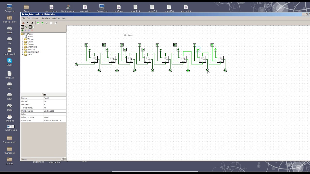
Full-adder circuit, the schematic diagram and how it works – deeptronicAdder vhdl designing 8bit compile simulate waveform verify program 11+ 4 bit adder circuit diagram8 bit adder circuit.
![11+ 4 Bit Adder Circuit Diagram | Robhosking Diagram](https://i2.wp.com/media.cheggcdn.com/media/69d/69d16419-1d4d-46a9-9669-f907cf2efd23/php4BG2gJ.png)
Adder bit circuit
Vhdl tutorial – 21: designing an 8-bit, full-adder circuit using vhdl .
.
![Download 4 bit adder circuit stick and logic diagram - Educative Site](https://i2.wp.com/educativesite.com/wp-content/uploads/2019/08/4-bit-adder-300x207.png)
![8 Bit Adder circuit - YouTube](https://i.ytimg.com/vi/CBENTjvkk3k/maxresdefault.jpg)
![VHDL Tutorial – 21: Designing an 8-bit, full-adder circuit using VHDL](https://i2.wp.com/www.engineersgarage.com/wp-content/uploads/2021/02/full-adder-8bit.png)
![6.4: 2-Bit Adder Circuit - Engineering LibreTexts](https://i2.wp.com/eng.libretexts.org/@api/deki/files/41933/2_bit_full_adder_circuit.png?revision=1&size=bestfit&width=654&height=789)
![Digital Logic Design: Full Adder Circuit](https://4.bp.blogspot.com/-NIy45k3TuEE/TkouUTvUOZI/AAAAAAAAAG8/SQiB48Yi_UQ/s1600/550px-Full-adder.png)
![Fitfab: 8 Bit Adder Truth Table](https://i2.wp.com/www.cise.ufl.edu/~mssz/CompOrg/Figure3.8-AdderCkt2.gif)
![logic gates - How to make 2 bit or more half adder circuit - Electrical](https://i2.wp.com/i.stack.imgur.com/Dj6XM.jpg)
![Full-Adder Circuit, The Schematic Diagram and How It Works – Deeptronic](https://i2.wp.com/www.deeptronic.com/wp-content/uploads/2019/09/4-bit-adder-circuit.png)